Click to enlarge pictures below.
The shack
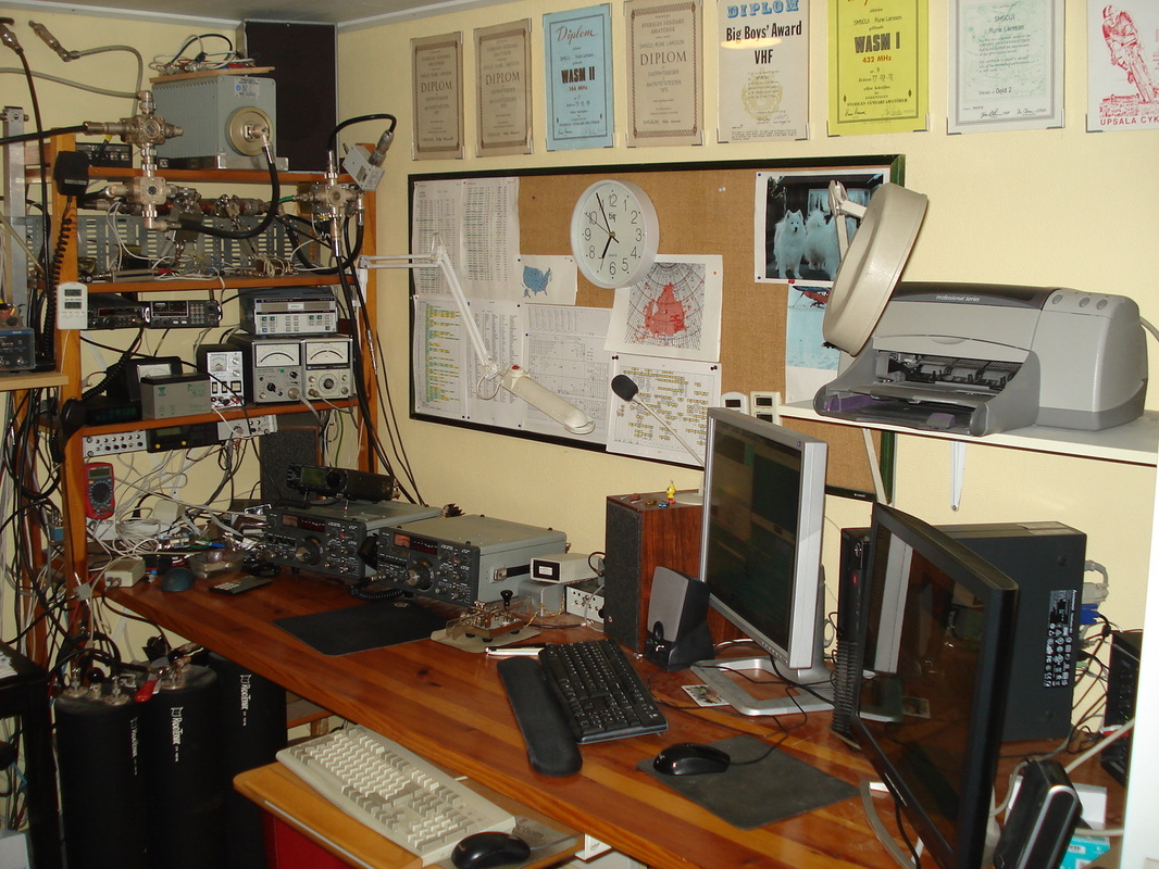
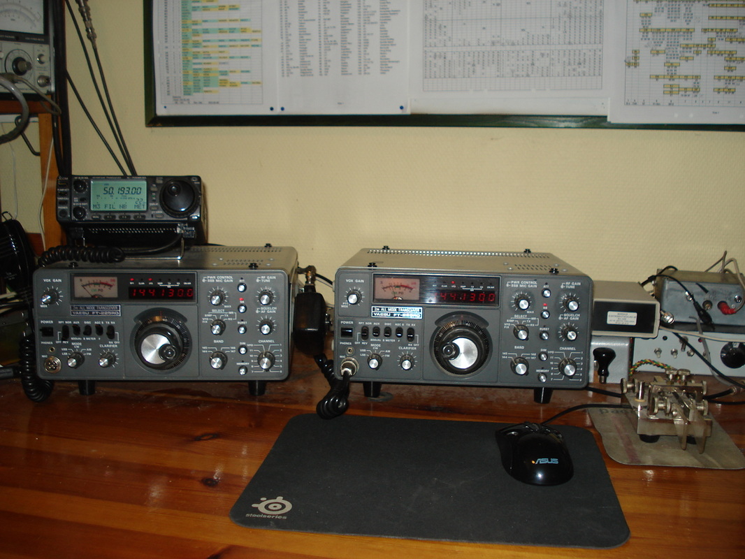
My old (but in good shape) rigs for 2m, and IC-706 MK IIG
TRX: FT 225 RD + Home made PA 2 x 4CX250B / 800 W out.
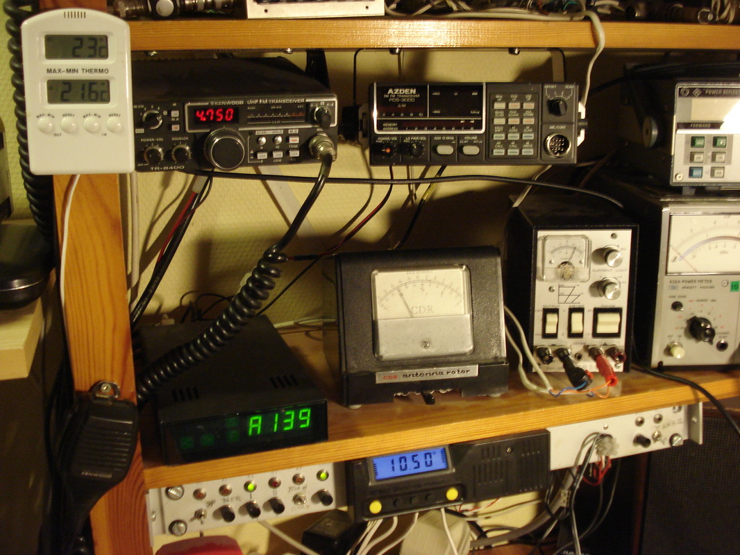
144 MHz RX 2 : FT 225 RD + 432 MHz FM TR 8400
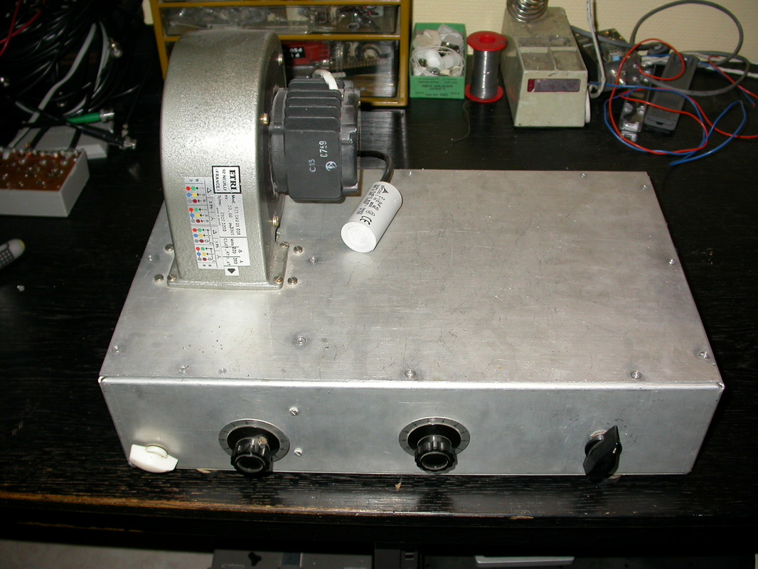
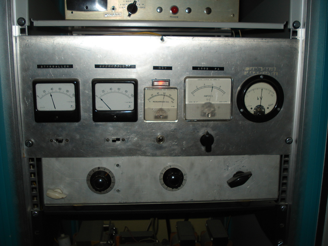
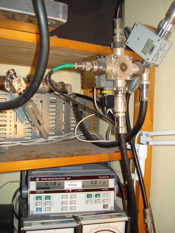
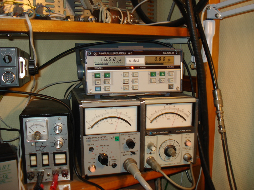
How I measure the drive power from TRX, output from PA and reflected pwr.
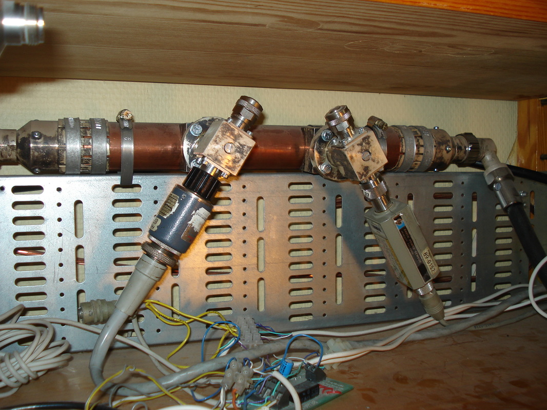
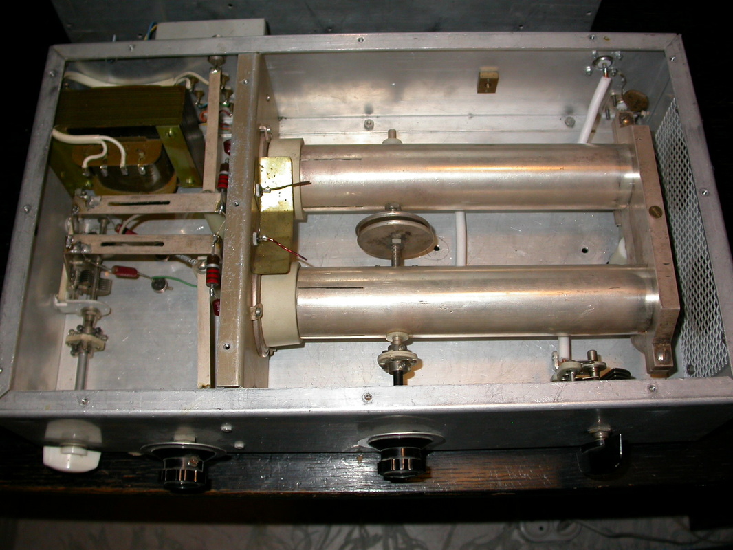
Home made calibrated directional coupler. 50 dB coupling factor at 144 MHz.
|
2 way switch. TRX or PA to antenna switch. R&S NAP _ HP 432 A _ HP 435 A Directional coupl. on station ground plate (earth)
2 way Coax switches Spinner BN 51 26 90__ http://www.telsat.it/uk/products-79-908.htm The upper switch: In to the Left = H-pol antenna. In to the Right = V-pol antenna. Top connected cable go to a small relay to protect the input of LNA-2. (MGF 1302) The coupling between the two antenna systems is abt 40 dB. 1 kW to either system = 60 dBm -40dB = 20 dBm = 100 mW= No good in to the LNA-2. Switch below is the TX/RX switch. In TX sequence the LNA is terminated by the dummy load. The LNA-1 to the right : ATF 54143 / 0.2 NF. 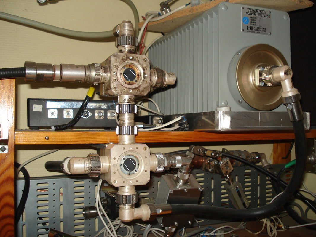
|